


123/SmartBMS
The amount of usable energy in a battery is expressed as state-of-charge, or SoC for short.
The value ranges from 0 – 100% where 0% means that the battery is fully discharged and 100% means that the battery is fully charged and, depending on the BMS type, also completely balanced.
SoC measurement methods
There are several methods for measuring and calculating the SoC:
Based on battery voltage
Advantages:
- Simple method of measurement
Disadvantages:
- Only works when the battery is at rest
- Does not work well with LiFePO4 as this technology has almost the same voltage between 40% and 80% SoC.
Based on measuring the chemical balance
Advantages:
- Accurate
Disadvantages:
- Invasive method requiring the cell to be opened up
- Difficult to apply
Measuring the current going into or out of the battery pack
This method is called coulomb counting. It essentially is the itegration of the measured currents over time. For example, if the system measures a discharge current of 2A for 4 hours, you have a total discharge of 2A x 4h = 8Ah.
Advantages:
- When the current meter is accurate, the SoC is also fairly accurate
- Non-invasive so easy to measure
Disadvantages:
- Only works if the current measurement is accurate
- When the SoC is not synchroniszed frequently by the BMS, the SoC may not be accurate anymore
Accurate results
Without an invasive method, the SoC cannot be determined directly under many circumstances. To still get reliable results, several methods must be combined, along with high-quality measuring equipment.
The 123\SmartBMS does this by using dual-range current sensors. This means that small currents in the range of mA’s can be measured up to very high currents like 500A. In addition, the BMS synchronizes the SoC at multiple voltages when the battery is at rest.
Useful information: as long as not all cells are over the full threshold, the battery is not properly balanced yet. The SoC will stay maximum at 99%. When all cell voltages are over the full threshold and when the charging power is low, the battery is fully charged and balanced, and the SoC will be synced to 100%.
Of course, do not forget to do the one-time calibration procedure for the current sensors after the installation. This ensures the most accurate current sensing result. See the 123\SmartBMS manual how to calibrate the current sensor.
It is best to use a current sensor that is close to the current that is most common in your set-up. Suppose the nominal current is 80A, with pieks of 150A, then you are best off with a current sensor of 100A. This will be more accurate in this working area than a current sensor of 250A.
The BMS cell boards work in a voltage range from 1,5V to 5V. Every cell that operates between this voltage should be compatible. A couple of working cell chemistry examples are LTO, LiFePO4, NMC and NCA.
It is possible to only use 1 current sensor, the BMS will also work perfectly fine. Using one sensor will use less power on the Begin Board. The drawback is that you cannot measure incoming and outgoing currents independently, but only see the current going in or out the battery pack. Connect the current sensor to Sensor 1 on the Begin Board and make sure to see a positive current in the App next to the battery icon when charging and a negative current when discharging.
There is a difference between placing multiple cells parallel or packs parallel.
Multiple cells parallel
You can safely place multiple cells parallel and only need 1 BMS cell module per parallel group. For instance: a 12V LiFePO4 pack consists of 4 cell groups in series. In case you have 8 cells, the pack is configured as 2P4S (groups of 2 cells parallel, then these parallel groups in series). In this case you only need 1 BMS for 4S (4 cell groups).

Multiple battery packs parallel
When you have to connect multiple packs parallel, you need 1 complete BMS per pack. You can connect the signal relays on each OUT board in series. For instance: with 3 packs parallel, you can run the charging signal through from the first OUT boa rd Charge relay to the second Charge relay and through the third Charge relay. This signal can switch an enable/disable or power relay. When one or more BMS have a cell charge error, the signal path is broken. The same goes for the Load relays in series.
No battery data on the app and the “E” sign will light ON in the battery details tab of the App. Check the flashing LEDs on the string of cells.
The BMS message starts at the Begin Board. When the next board received the message, the LED will flash and the board will send the message to the next board.
The position where the LED stops flashing is the location of the problem. It can be that board or the previous board. Check if the communication wire goes from the “OUT” in the previous board to that board’s “IN” connector.
Make sure there is running absolutely no current through the current sensors during the zero calibration procedure.
On the Begin Board you will find a blue button. Press and hold the blue button until the LED flashes fast. Now release the button. The calibration is done.
While the Begin Board is connected to the battery cell, press and hold the blue button for 5 seconds. The PIN will be set to the default “1234”.
Make sure your phone supports Bluetooth 4 or higher.
Android 7.0 contains a bug which can make it impossible to connect to the BMS. If your phone has Android 7.0, please check and update the Android version if this is possible. For help regarding updating the Android version, please contact your phone manufacturer.
The following steps can help to connect to the BMS.
If you have Android, make sure you have wireless connection AND location turned on.
Restart the App and check in de Settings screen if the BMS appears under “Devices”. Tap on it to connect.
Restart your phone and open the App to check again.
Try a different phone, download the 123SmartBMS app and check if you see the BMS in the device list.
While the End Board is powered, hold the blue button for 5 seconds. The PIN number will reset to the factory default (1234) and after approximately 10 seconds the Bluetooth module is reset.
The 123\SmartBMS has Bluetooth Low Energy. To get a list of devices nearby, the app asks Android to scan for Bluetooth Low Energy devices. Android only starts scanning for these devices if location permission is turned on. Otherwise, the app will get an empty list.
When you turn the location permission on, the app will get a list of BLE devices that are close enough, like 123\SmartBMS.
The app does not use or store the location in any way.
This depends on the application. We always recommend a power efficient relay which consumes low energy when turned on.
Recommended relays:
Yes, the boards are designed so the + pole can be drilled bigger if needed.
Very small currents cannot be measured by the current sensor, so the BMS will not update the SoC. Only when one of the cells is below Vmin, the SoC will be recalibrated to 0% because this is a known point to be empty.
Make sure the pack is charged regularly so the SoC is recalibrated to 100% when full.
If you are not going to use the pack for a longer time (for example because it is winter), you can disconnect all loads so the pack will not be drawn until empty. You can also connect a small trickle charger to prevent the batteries from being discharged during standby.
Victron GX
Most Victron devices can be controlled via a GX, for example the CCGX and Cerbo GX. The GX sends the correct info to the charger/inverter, for example to the Quattro.
Some devices even have a GX integrated, for example the Multiplus GX. This saves on adding an external GX.
By combining a 123\SmartBMS with the Victron GX, it is possible to control the connected Victron devices by the 123\SmartBMS.
In any case, always add an energy efficient power relay to the 123\SmartBMS signal relay(s). This ensures that the BMS is able to disconnect all connected loads/chargers in case of an emergency, thus protecting the batteries at all times.
Setup the Victron device with VEConfig
If your device is not configured for control by the GX, then make sure to do this.
The following step describes the configuration of a Phoenix/Multiplus/Quattro with VEConfig.
Step 1. Use the MK3-USB and connect it to the Victron device. Download and install Victron VEConfig.
Step 2. Add the ESS Assistant
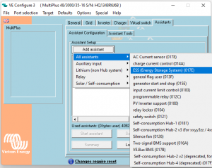
Step 3. Start the assistant. Select “Other BMS”.

Continue until the assistant is finished.
Step 4. Send the settings to the target.
Connect the 123\SmartBMS to the Victron GX.
Step 1. Download and install the 123\SmartBMS made “venus-data.tar.gz” software which can be found here. Put it on an empty FAT32 formatted USB drive. Do not extract the file.
Step 2. Plug the USB drive into a Victron GX USB data port.
Step 3. Reboot the GX. The software is now copied. After the GX is restarted, you can remove the USB drive.
Step 4. Reboot again. The software will install after the reboot.
Step 5. Connect a 123\SmartBMS to USB cable from the 123\SmartBMS End Board Ext Data port to the Victron GX USB port. After several minutes, you should see a 123\SmartBMS instance appear on the remote console and VRM.
Note: if you have the Victron Cerbo GX, only two out of three USB ports work – the data ports
Enable DVCC on the Victron GX
Open the Victron GX remote console, either via LAN or via VRM. Go to Settings->DVCC. Enable DVCC.
Also enable SVS and STS. This ensures that the BMS measured voltage and temperature are used by the Victron system.
First set the correct absorption voltage. The end/absorption voltage needs to match the battery pack to operate correctly. For example: if you have 4 cells and the balance voltage (Vbalance) is 3.4V, the pack balance voltage is 3.4V x 4 cells = 13.6V. You need to configure the charger to an end/absorption voltage a bit higher (about 0.2V) than this voltage which is 13.8V.
Device with remote signal
Many Victron devices have a “remote” or “enable” signal which consists of two wires. As long as the two wires are connected to each other, the device will be enabled. When the signal path is broken, the device will switch to standby mode. This “remote” signal can directly be connected to the SmartBMS signal relay.
For example if you have an inverter with a remote port, you can wire the two remote wires to the Discharge/Load signal relay potential free contacts located on the End Board (last cell board). Use connector pin 1 and 2, which are “allow to charge” and “common contact”.
Victron BlueSolar and SmartSolar MPPT Charge controller
Use the Victron VE.Direct non inverting remote on-off cable, part number ASS030550310. With this cable, you can connect the battery + to pin 2 (common contact) of the Charge signal relay of the SmartBMS. Connect the Victron yellow remote cable to the SmartBMS Charge contact pin 1 (allow to charge). Also see the Victron document.
Victron without GX or “remote” control
If your Victron device does not have a remote control signal and cannot use the VE.Direct non inverting remote on-off cable, you can still connect a power efficient power relay to the BMS so the BMS can switch off the device in case this is needed. See the manual for a general schematic.
It is possible to use a combined charger/inverter. Just use 1 current sensor and connect this sensor to sensor 1. Make sure to run the current cable the right way through the current sensor. When charging, you should see a positive current in the app next to the battery icon. When discharging, you should see a negative current.
Combined charger/inverter with two enable/disable signals, one for charger and one for inverter
You can keep the BMS in “normal mode” and use the charge relay for the enable/disable signal of the charger and the load relay for the enable/disable signal of the inverter.
Combined charger/inverter with 1 enable/disable or no enable/disable signal
In ”normal mode” the BMS will switch off the charge relay when the battery pack is full. However, this would mean the shared power will be switched off and the user is not able to discharge. For this case the BMS can be configured in “critical mode”. The BMS will only switch the power off in case there is a critical error condition.
You can change to Critical Mode at Settings in the app.
Connect the charge and load relay of the BMS in series to get a combined charge/load signal. Now you can switch a power relay or the enable/disable signal of the device.The charger/inverter bulk/end/absorption voltage needs to match the battery pack to operate correctly. For example: if you have 4 cells and the balance voltage (Vbalance) is 3.4V, the pack balance voltage is 3.4V x 4 cells = 13.6V. You need to configure the charger to a bulk/end voltage a bit higher (about 0.025V-0.04V higher per cell) than this voltage which is 13.8V. For 16 LiFePO4 cells, this is 54.8V-55.0V.

The 123\PowerSwitch can be used to switch off one or more loads/chargers and can be controlled by the 123\SmartBMS.
There are two configurations possible:
Use one 123\PowerSwitch for the whole installation
In this configuration, the 123\PowerSwitch will be used as “last line of defense”. When a cell has an error, for example when a cell voltage is too high or too low, the PowerSwitch will be turned off and thus all connected chargers and loads will be disconnected from the battery. When the error is gone, the PowerSwitch turns on again.
This configuration is mostly used with combined chargers/inverters which is a setup where the charger and inverter are in the same device like the Victron Quattro/Multiplus.
Connect the 123\PowerSwitch black control wire (negative) to the battery pack negative.
Connect the 123\PowerSwitch red control wire to the “common contact” of the End Board Charge signal relay potential free contacts.
Connect the End Board Charge signal relay “allowed to charge” to the Load signal relay “allowed to discharge”.
Connect the End Board Load signal relay “common contact” to the battery pack +.

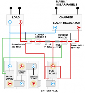
Use two 123\PowerSwitches: one for all chargers and one for all loads/inverters
The benefit of this configuration is that when one PowerSwitch is off, for example the “allowed to discharge”, the other PowerSwitch (“allowed to charge”) stays on. Thus if a battery cell is empty, the charger will stay connected to charge the pack.
Connect a wire from the battery pack + to the “common contact” (middle hole) of the Load signal relay and to the Charge signal relay.
Connect the 123\PowerSwitch black control wire (negative) of both PowerSwitches to the battery pack negative.
Connect the End Board Charge signal relay “allowed to charge” pin to the charge 123\PowerSwitch red control wire.
Connect the End Board Load signal relay “allowed to discharge” pin to the discharge 123\PowerSwitch red control wire.
The Victron BatteryProtect can be used to switch off one or more loads/inverters and can be controlled by the 123\SmartBMS.
Connect the BatteryProtect Remote wire 1 to SmartBMS End Board Load relay “common contact” (pin 2). Connect the BatteryProtect Remote wire 2 to SmartBMS End Board Load relay “allow to discharge” (pin 3). When discharging is allowed, Remote pin 1 and Remote pin 2 are connected to each other to let the BatteryProtect know charging is allowed.
